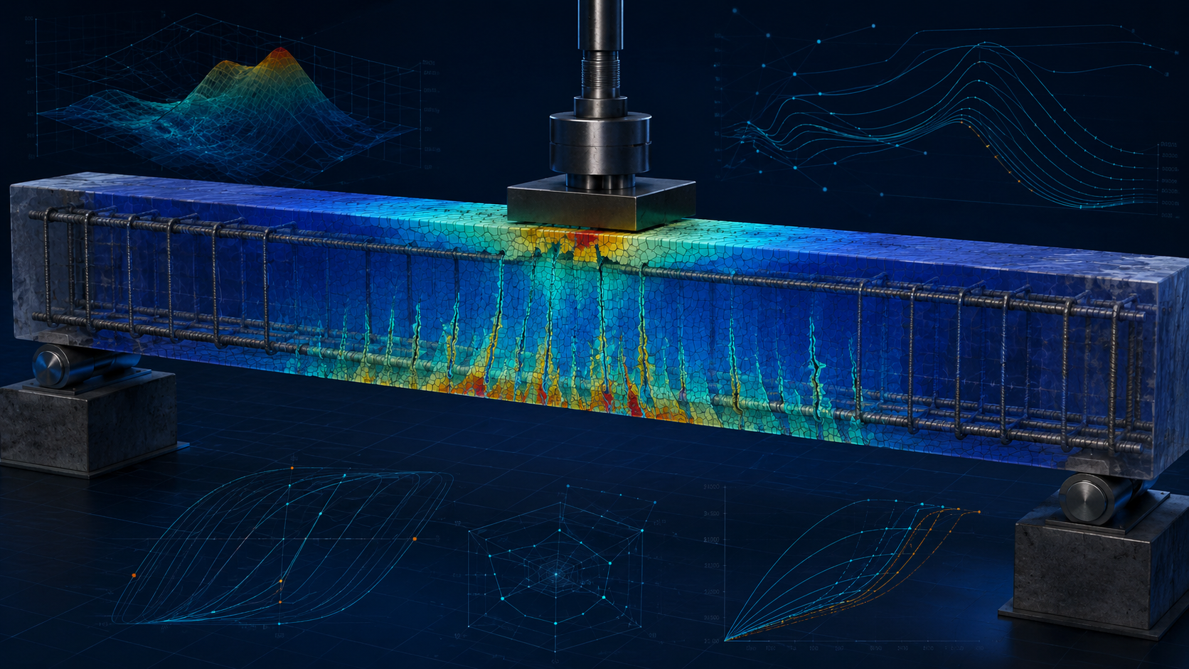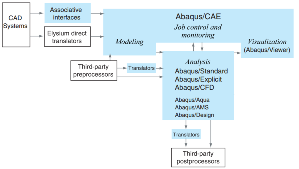

CONWEP blast loading in Abaqus provides an efficient way to apply an empirically defined air-blast or surface-blast pressure field to a structural model without explicitly meshing the explosive and surrounding air domain. The method is especially useful for short-duration structural-response studies in Abaqus/Explicit, but a reliable model requires more than entering a TNT mass and running the job. Charge definition, source geometry, standoff distance, the selected blast idealization, structural boundary conditions, mesh density, Explicit stability, and validation must be checked as one engineering workflow.
This guide is written for researchers, postgraduate students, and practising engineers who need to define a CONWEP load in Abaqus and, more importantly, defend the modelling assumptions and numerical checks behind the result.
The goal is not merely to obtain a deformed contour. The goal is to create a blast-response model in which the load definition, units, structural idealization, numerical stability, and validation evidence are traceable.
1. Start with the engineering problem
Before opening the Interaction module, define the quantity that the analysis is intended to predict. Peak displacement, permanent deformation, support reaction, concrete damage, local rupture, connection failure, and global frame response are different engineering objectives. A model that is adequate for maximum midspan displacement may be inadequate for predicting fracture or local damage.
Document the structure, blast source, response quantity, and validation reference before building the final analysis. For the structure, record dimensions, thicknesses, support conditions, joints, and relevant secondary components. For the blast source, record the explosive basis, TNT-equivalent mass, assumed source location, and whether the event is idealized as an air blast or surface blast. Finally, identify the measured or independently estimated response that will be used to judge the model.
2. Decide whether CONWEP is the right loading method
In Abaqus/Explicit, CONWEP is available through the incident-wave framework for air-blast and surface-blast loading. It can apply air-blast pressure loading to structural or solid elements without explicitly modelling the surrounding fluid medium. This can reduce model size and computational cost substantially when the primary research question concerns structural response rather than detailed blast-wave propagation.
That efficiency also defines the method's modelling boundary. CONWEP should not automatically replace a coupled fluid-structure, acoustic, Eulerian, ALE, or CEL approach when the research question depends on highly confined blast behaviour, detailed wave diffraction, shielding by major obstacles, repeated reflections in complex spaces, or explicit interaction between the pressure wave and a surrounding fluid domain.
Use CONWEP when the structural response to an idealized air or surface blast is the primary problem. Consider a more detailed propagation model when the evolution of the blast wave itself is a controlling part of the research question.
3. Define the blast scenario before defining the interaction
A reproducible blast model should include a compact scenario table. This prevents the analyst from mixing values taken from different unit systems or experimental cases.
| Parameter | Model value |
|---|---|
| TNT-equivalent charge | [enter value and unit] |
| Explosive equivalence basis | [source or assumption] |
| Blast source coordinates | [X, Y, Z] |
| Minimum standoff distance | [enter value and unit] |
| Blast type | Air blast / Surface blast |
| Model unit system | [document the complete consistent unit system] |
| Time of detonation | [enter value] |
| Explicit step duration | [enter value] |
| Primary validation quantity | [displacement, strain, failure mode, etc.] |
4. CONWEP inputs required in Abaqus
The core load definition is controlled by a small number of inputs, but every input has a physical meaning. Verify the TNT-equivalent charge mass, source coordinates, standoff distance, air-blast or surface-blast assumption, exposed structural surface, time of detonation, magnitude scaling required by the model unit system, and the analysis duration.
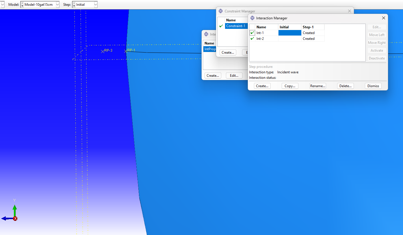
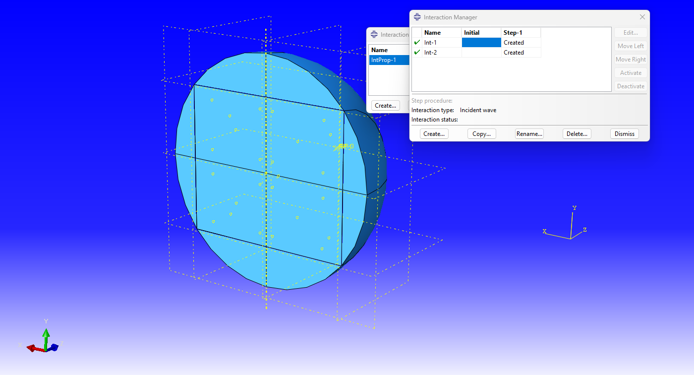
In Abaqus/CAE, the incident-wave interaction uses a blast source point and an exposed surface as separate definitions. The source reference point defines where the charge is located. The selected surface defines where the pressure is evaluated and applied. Confusing these two definitions is a common source of incorrect spatial loading.
5. Charge weight and TNT equivalence
CONWEP blast scenarios are commonly described using a TNT-equivalent charge. When the physical explosive is not TNT, the actual charge mass may be converted using an adopted relative effectiveness or equivalence factor. A simplified expression is:
where WTNT is the TNT-equivalent mass, Wexplosive is the actual explosive mass, and RE is the adopted equivalence factor.
The word adopted matters. An equivalence factor should not be copied from an unrelated study without checking what quantity was used to establish equivalence. Depending on the methodology, equivalence may be associated with pressure, impulse, energy, or a specific experimental calibration. A thesis or research article should cite the source and explain the selected basis.
6. Standoff distance and blast-source geometry
Standoff distance is the distance between the blast source and the structural target. In a simple plate model this may be measured from the source to the plate centre. In a three-dimensional structure, however, different points on the exposed surface have different distances and orientations relative to the source. The source must therefore be positioned using the actual assembly coordinates.
One of the easiest mistakes to make is calculating the correct standoff on paper but placing the reference point in inconsistent model units. If a millimetre-based model requires a source 2 m from a wall, the coordinate distance is 2000 mm, not 2.
A useful comparison parameter is the Hopkinson-Cranz scaled distance:
where R is the standoff distance and W is the TNT-equivalent charge mass. Scaled distance is useful when comparing blast scenarios, but it is not a substitute for verifying the actual source coordinates and exposed geometry in the Abaqus assembly.
7. Incident pressure and reflected pressure are not interchangeable
Incident pressure describes the pressure associated with the propagating blast wave before interaction with the target. Reflected pressure develops as the wave interacts with a surface and depends on the orientation and interaction of the wave with that surface.
A common modelling error is to take a reflected pressure from a chart, apply an additional reflection factor, and then also use a CONWEP incident-wave interaction without checking whether the load has effectively been counted twice. When the built-in CONWEP workflow is used, treat the spatial blast definition as a complete load idealization and do not manually apply arbitrary reflection multipliers unless the loading method has intentionally been reformulated and independently justified.
8. Apply CONWEP blast loading step by step
Step 1 — Complete the structural model
Create the geometry, materials, sections, assembly, connections, boundary conditions, and the exposed structural surface before defining the blast load. The blast interaction should not be used to hide an incomplete structural idealization.
Step 2 — Create the blast source reference point
Create a reference point at the intended charge location and record its coordinates. Independently calculate the intended standoff distance and compare it with the model geometry. A useful verification note is simply:
Blast source RP
X = [value]
Y = [value]
Z = [value]
Minimum standoff = [value]
Step 3 — Create a Dynamic, Explicit step
Blast response is a short-duration, high-rate dynamic problem. The total step duration should be selected from the engineering objective, not only from the duration of the positive pressure pulse. If permanent deformation is the validation quantity, the simulation may need to continue until the response has developed sufficiently to identify the residual state.
Step 4 — Define the incident-wave interaction property
Create the incident-wave interaction property and select the appropriate air-blast or surface-blast definition for the assumed physical event. The selected blast type is an engineering assumption and should be stated in the report.
Step 5 — Define the CONWEP charge
Enter the TNT-equivalent charge magnitude and check its compatibility with the analysis unit system and the reference magnitude or scaling used by the incident-wave definition. Do not rely on a job completing successfully as evidence that the units are correct.
Step 6 — Create the Incident Wave interaction
In the Dynamic, Explicit step, create an Incident Wave interaction, select the source reference point, select the CONWEP definition, choose the exposed structural surface, assign the blast interaction property, and specify the time of detonation and reference magnitude or scaling information required by the model.
9. Units and pressure-time history
Abaqus does not enforce a universal unit system. Geometry, density, elastic modulus, time, mass, and every load-related value must form a consistent mechanical unit system. Blast models are particularly sensitive to unit errors because charge mass, source geometry, and short time scales are combined in one transient calculation.
When the built-in CONWEP incident-wave definition is used, do not also create a manually entered pressure-time amplitude unless you are intentionally building a different loading method. A manual pressure-time curve may be appropriate when measured pressure data are available, a code-derived history must be imposed directly, or a published loading function is being reproduced. That is a different workflow and should be documented as such.
10. Explicit step controls, contact, and boundary conditions
A correct blast definition cannot rescue an incorrect structural model. Supports should reproduce the experimental specimen or actual structural system to the degree required by the research objective. A perfectly fixed plate edge is not automatically equivalent to a bolted test frame, a clamped fixture, or a deformable connection.
When calculated deformation is lower than experimental deformation, do not immediately increase the blast load. First examine support flexibility, material strain-rate assumptions, connection behaviour, mesh sensitivity, and the failure mechanism.
Contact should be defined where separation, collision, folding, self-contact, or component-to-component impact is physically possible. Review initial penetrations, contact surfaces, friction assumptions, contact energy, and numerical noise. In severe transient models, contact behaviour can also influence numerical stability and computational cost.
11. Mesh strategy and the Explicit time increment
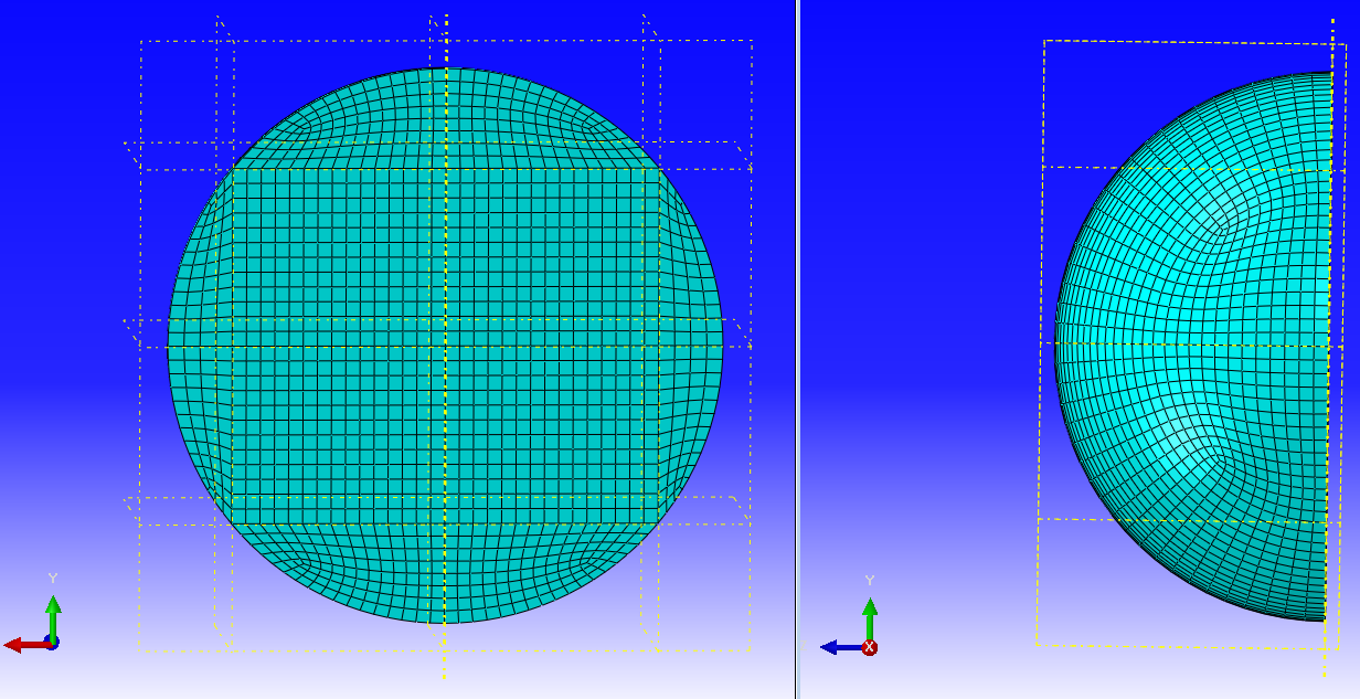
There is no universal element size for blast analysis. Mesh density should be selected according to the response quantity, structural dimensions, element formulation, thickness, material model, expected deformation mode, and local response gradients. A mesh that is sufficient for global displacement may still be inadequate for local strain or damage prediction.
Use at least three mesh levels when the result is sensitive to spatial discretization:
| Mesh level | Relative density | Primary use | Acceptance check |
|---|---|---|---|
| Coarse | Baseline / larger elements | Initial response screening and model debugging | Establish the trend; do not use alone for local damage conclusions |
| Medium | Reduced element size | Main engineering response assessment | Compare peak and residual response with the coarse mesh |
| Fine | Further local refinement | Convergence confirmation in critical regions | Accept when the selected engineering response changes only marginally |
Compare the engineering quantity that matters: peak displacement, residual displacement, plastic strain, damage, reaction, or another defined validation output.
In Abaqus/Explicit, the stable time increment is strongly influenced by element characteristic size and the current dilatational wave speed. A very small or poorly shaped element may control the time increment of the entire model and dramatically increase run time. Before using mass scaling, inspect the elements controlling the smallest increments and decide whether they are physically necessary or the result of poor meshing.
12. Energy balance and numerical stability
Never accept a blast model by looking only at a deformation contour. Request whole-model energy history output and review the evolution of kinetic energy, internal energy, artificial strain energy, plastic dissipation, external work, and relevant contact-energy terms.
ALLKE— kinetic energyALLIE— internal energyALLAE— artificial strain energyALLPD— plastic dissipationALLWK— external work
Artificial energy should be monitored, particularly with reduced-integration elements. Avoid using a single universal percentage as an automatic pass/fail criterion for every model. The engineering question is whether artificial or stabilization-related energy is small enough that the structural response is not being controlled by a numerical mechanism.
For a plastically deforming structure, compare the work introduced by the blast with the energy absorbed through structural response. Unexpected energy jumps, unexplained growth in artificial energy, or a response dominated by numerical stabilization require investigation before validation.
13. A practical validation workflow
Level 1 — Input verification
Check the TNT-equivalent charge, source coordinates, standoff distance, blast type, unit system, time of detonation, and exposed structural surface.
Level 2 — Load-response sanity check
Verify the deformation direction, spatial location of the maximum response, timing of the response, and absence of unexplained initial motion.
Level 3 — Mesh sensitivity
Repeat the calculation with a refined mesh and compare the selected engineering output.
Level 4 — Numerical checks
Review energy histories, excessive element distortion, contact behaviour, stable time-increment information, and any mass scaling.
Level 5 — Physical validation
Compare against experimental displacement, permanent deformation, a measured failure pattern, a published benchmark, an analytical estimate, or another independently validated model. A discrepancy should be discussed rather than hidden. Boundary-condition stiffness, material behaviour, connection assumptions, and experimental uncertainty are all legitimate sources of disagreement that must be evaluated.
14. CONWEP limitations and cases that need another method
CONWEP is powerful when its idealization matches the problem. Use additional caution for highly confined blast, complex enclosed spaces, major shielding obstacles, repeated wave reflections, explicit explosive detonation physics, detailed wave diffraction, or problems in which the surrounding medium and fluid-structure interaction are themselves central research variables.
The correct question is not simply whether CONWEP is accurate. The better question is whether the CONWEP idealization represents the physical mechanism that controls the result you are trying to predict.
15. Common errors and troubleshooting
Incorrect units
Symptom: unrealistically large deformation, negligible response, or a physically unreasonable time scale. Check: geometry, density, elastic modulus, charge scaling, source coordinates, and the complete unit system.
Wrong blast-source position
Symptom: the maximum response occurs in an unexpected region. Check: source reference-point coordinates and assembly orientation.
Incorrect exposed surface
Symptom: the wrong face is loaded or a part of the target receives no blast load. Check: surface definitions and shell-face orientation where applicable.
Overly stiff boundary conditions
Symptom: displacement is consistently smaller than experimental results. Check: support flexibility, clamps, bolts, welds, and test-frame deformation before changing the blast load.
Refining the entire model
Symptom: the stable time increment becomes extremely small and computational cost increases disproportionately. Check: which elements control the stable increment and refine only where the selected response quantity requires it.
No energy review
Symptom: the deformation contour looks reasonable, but the numerical quality of the solution is unknown. Check: ALLAE, ALLIE, ALLKE, ALLWK, ALLPD, and relevant contact-energy terms.
Changing the blast load only to force agreement
Symptom: charge mass or standoff distance is repeatedly modified until a numerical displacement matches a test. Check first: material strain-rate behaviour, supports, mesh, failure criteria, connection flexibility, and experimental uncertainty. Calibration is not the same as forcing agreement.
16. Related numerical model
Steel Plate Subjected to Underwater Explosion using ABAQUS
Researchers studying short-duration pressure loading and transient plate response may also find the Numerical Archive steel-plate explosion model useful as a validated structural-response reference.
Important: this product is an underwater-explosion (UNDEX) model. It is not presented as a CONWEP air-blast template, and its fluid-loading assumptions should not be transferred directly to a CONWEP analysis.
17. Engineering checklist before the final job
- TNT-equivalent charge is documented.
- The equivalence-factor source is identified where applicable.
- Blast source coordinates are recorded.
- Standoff distance is independently checked.
- Air-blast or surface-blast assumption is justified.
- The exposed structural surface is verified.
- The complete model unit system is documented.
- The Dynamic, Explicit step duration captures the required response.
- Contact definitions represent possible physical interaction.
- Boundary conditions represent the real system or validation specimen.
- The material model is appropriate for the expected rate and failure regime.
- Critical response regions are sufficiently refined.
- Accidentally tiny controlling elements have been investigated.
- Mesh sensitivity is evaluated using a relevant output.
- Stable time-increment behaviour is reviewed.
- Peak and residual response are distinguished.
ALLIE,ALLKE,ALLAE,ALLPD, andALLWKare reviewed.- Artificial energy does not dominate the response.
- Contact behaviour is checked.
- The result is compared with an independent validation reference.
18. Final recommendations
A reliable CONWEP analysis is built from a verified blast scenario, not from a software command. The modelling sequence should remain traceable from the physical problem through the final validation evidence.
For a research paper, thesis, or engineering report, state the TNT-equivalent charge, show the source coordinates, report the standoff distance, identify the blast definition, document the unit system, explain the mesh, plot the energy histories, and compare the structural response with an independent reference.
That is the difference between running a CONWEP model and defending a CONWEP model as an engineering analysis.
References
- Dassault Systèmes SIMULIA — Defining incident waves in Abaqus/CAE.
- Dassault Systèmes SIMULIA — *INCIDENT WAVE INTERACTION keyword reference.
- Dassault Systèmes SIMULIA — Acoustic and shock loads; CONWEP air-blast loading in Abaqus/Explicit.
- Dassault Systèmes SIMULIA — Explicit dynamic analysis and stable time-increment estimation.
- Dassault Systèmes SIMULIA — Total energy output in Abaqus/Explicit.
- UFC 3-340-02 — Structures to Resist the Effects of Accidental Explosions.