Introduction
One of the most widely used software in the field of finite element analysis is Abaqus software. This software was created in 1987 by David Hibbitt, Ben Carlson and Paul Sorensen; It was originally designed for use in nuclear power and drilling engineering. Because engineers in these branches needed a tool to study complex and non-linear problems. Since this software is based on non-linear problems, it has a high ability to simulate the real world. This software gives the user the ability to model the most complex phenomena by considering very subtle effects. Thus, with the development of a wide range of industries in the years 1980 to 1990, this software found a special place as the selected software among other finite element software's for users.
Considering that Abaqus is a general and extensive modeling tool, its usage is not limited to the mechanical analysis of solids and structures (stress-displacement). Using this software, it is possible to study various issues such as heat transfer, mass penetration, thermal analysis of electrical components, acoustics, soil mechanics and piezoelectricity.
Using the Abaqus software is a relatively simple task, even though it provides a wide range of features to the user. The most complex problems can be modeled easily. For example, issues involving more than one component can be modeled by creating a geometric model of each component, attributing the behavior of the corresponding material to those components, and then assembling different components. In most modeling, even models with a high degree of non-linearity, the user should only determine the engineering data such as the geometry of the problem, the behavior of the related material, the boundary conditions and the loading of that problem. In a non-linear analysis, Abaqus automatically selects the rate of load growth and convergence tolerances and finally adjusts their values during the analysis to achieve a correct answer. As a result, the user rarely has to determine the values of the control parameters of the numerical solution of the problem.
Based on the recommendations of the software guide, the principles governing any finite element analysis in this software engineering tool include the following three steps;
- Preprocessing
- Problem Solving
- Postprocessing
In general, ABAQUS is a set of effective simulation programs based on the finite element method, which is capable of solving relatively simple linear problems to complex non-linear problems. ABAQUS includes a wide range of different elements that can be used to model any type of geometry. It also has different models of materials that can be used to model the behavior of most common engineering materials such as metals, rubber, hyperelastics and soil. Designing the software as a simulation tool with a general purpose has given it the ability to be used in problems beyond structural problems (stress/displacement). Therefore, this tool has become widespread among researchers and engineers, and a significant growth can be seen in the number of its users every day. In the following, we introduce some subsets and common terms of this engineering tool.
Subsets of ABAQUS
ABAQUS consists of two main subsets named ABAQUS/Standard and ABAQUS/Explicit. There are three other subsets for specific analyzes for ABAQUS/Standard, which are ABAQUS/Design, ABAQUS/Aqua and ABAQUS/Foundation. Also, ABAQUS interface with MSC.ADAMS and MOLDFLOW are MOLDFLOW and ADAMS/Flex respectively.
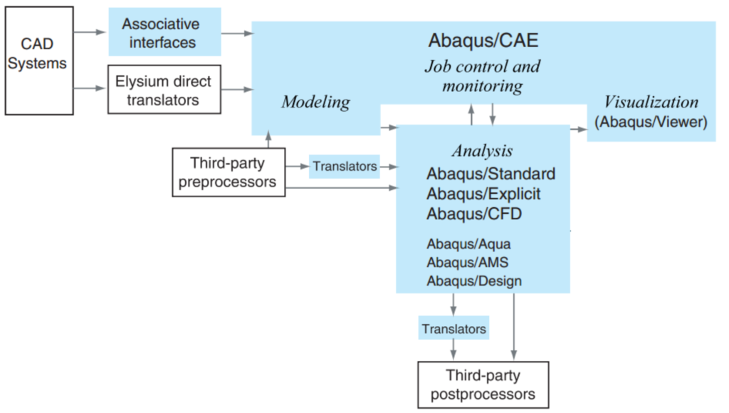
ABAQUS/CAE is a complete environment in ABAQUS that includes features for model creation, analysis and control, as well as checking the results. ABAQUS/Viewer is a part of ABAQUS/CAE that only includes processing and viewing results. The connection between different parts of this software is shown in the figure below;
ABAQUS/Standard
It is a general purpose processor (solver) and also is a sub-program to solve a wide range of linear or non-linear problems including static, dynamic, thermal and electrical states. The ABAQUS/Standard machine solves the equations in a implicit method in each step .
ABAQUS/Explicit
It is a subset for performing specific analyzes that uses explicit dynamic finite element formulas to solve problems. And it can be used to model transient and short dynamic events such as impact and explosion problems, as well as for situations with a high degree of non-linearity such as forming simulation.
ABAQUS/CAE (Complete Abaqus Environment)
This is a subset of the graphical environment of the software. This environment allows the user to create the model quickly and conveniently by creating or entering the model geometry. In this environment, physical properties and material properties along with loading and boundary conditions can be assigned to the geometry of all model’s parts. When the model is complete, ABAQUS/CAE records the analysis and allows the user to view the analysis process even during the analysis. Visualization module in ABAQUS/CAE is used to view and check the final results.
ABAQUS/Viewer
It is a subset of ABAQUS/CAE that is used only for processing analysis outputs.
ABAQUS/Aqua
It is a subset that is added to ABAQUS/Standard. It can be used to simulate offshore structures like oil and gas extraction platforms. Some of the capabilities of this sub-set are considering wave, wind, flow and buoyancy loading.
Element in ABAQUS
Considering the importance of the mesh technique and the type of elements, user should have more information about the elements. Therefore, in this section, we will describe the characteristics of elements and the theoretical explanations of them.
A wide range of elements can be used in ABAQUS, which gives the user great ability to model and analyze different types of problems. Now we get to know the five characteristics of an element that determine its behavior.
Each element has the following five characteristics;
- Family.
- Degrees of freedom (which directly depends on the element family).
- Number of nodes.
- Formulation method.
- Integration method.
Each element in ABAQUS has a unique name, such as S4R, T2D2 or C3D8I. It should be noted that the name of an element represents all five properties. Now let's examine each of the mentioned features;
Family of elements
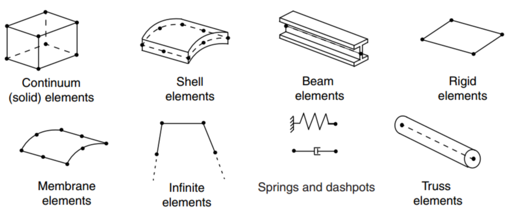
In the figure below, you can see the types of element families that are used in stress analysis problems. One of the main differences between the elements of two families is the type of geometry of the elements of those families. In the following, you will get acquainted with the characteristics of several families of the mentioned elements. The first letter or letters seen in the name of an element indicates the family of that element. For example, in the element “S4R”, the letter “S” indicates that this element is from the “Shell” family, and in the case of the element “C3D8I”, the letter “C” indicates that this element is from the “Continuum” family.
Degrees of freedom
The degrees of freedom are actually the main variables of each problem that are calculated during the analysis. For stress-displacement problems, the main degrees of freedom are the displacements of the nodes. It is necessary to mention that regarding the Shell and Beam elements, the rotation in the nodes is also of degrees of freedom, but according to the software guide, in a heat transfer problems, temperature of the nodes are one of their degrees of freedom. Therefore, it is clear that different elements should be used for a heat transfer analysis than the elements of a stress analysis. The following numbering system is used to represent degrees of freedom in ABAQUS:
1 Translation in direction “1”.
2 Translation in direction “2”.
3 Translation in direction “3”.
4 Rotation around axis “1”.
5 Rotation around axis “2”.
6 Rotation around axis “3”.
7 Twisting around “1” in the section of a Beam element.
9 Acoustic or net pressure.
10 Electric potential.
The symbols are different for axisymmetric elements. In these elements, the translation and rotation are symbolized as follows;
1 Translation in direction “r”.
2 Translation in direction “z”.
3 Rotation in “r-z” plane.
Note: r and z directions are radial and axial directions, respectively.
Basics of Abaqus
Abaqus software can perform various types of analysis and in this article, we just evaluate two types of static and dynamic analysis. In a static analysis, the long-term response of the structure is obtained for applied loads. In other cases, the dynamic response of structures is desired. For example, a sudden loading on one of the components that occurs when an impact occurs or the structure's response to an earthquake.
A complete analysis in the Abaqus program usually consists of three steps;
- Pre-processing step
- Processing step
- Post-processing step
These three steps are related to each other by a number of files according to the following process.
Pre-processing step in ABAQUSE/CAE software or other software; Input file named Job.inp, Job.CAE and Job.jnl.
Processing step with ABAQUS standard/explicit.
post-processing step in the software; Job.fil, Job.res, Job.dat, Job.odb output files.
Pre-processing in ABAQUSE/CAE
In this step, you should build the physics of the problem and create an Abaqus input file. The model can usually be created graphically using Abaqus or other preprocessors. It is necessary to explain that it is also possible to generate the Abaqus input file using a text editor such as Notepad.
Processing (standard/explicit) ABAQUS
Processing, which usually runs as a process in the background, is the step in which Abaqus solves the standard/explicit numerical problem defined in the modules. Examples of the output of stress analysis include displacements and stresses that are stored in binary files and used for the post-processing step. Depending on the complexity of the problems to be analyzed and the power of the computer that performs the analysis, the analysis time can take time from few seconds to few days.
Post-processing stage (ABAQUS/CAE).
The final result can be evaluated after the completion of processing step, i.e., when the stresses, displacements and other basic variables have been calculated. Evaluation is usually available using the visible output module (graphics module) or other post-processors. The graphics module reads the data of the binary output file and has different options such as colored contours, animation, deformation shape and displaying X-Y curves as results. The Abaqus model consists of many different components and these components together form the physical problem that needs to be analyzed. In the simplest case, the analytical model includes information such as separate geometry, characteristics of the elements cross section, material data, loads and support conditions, analysis type and required outputs.
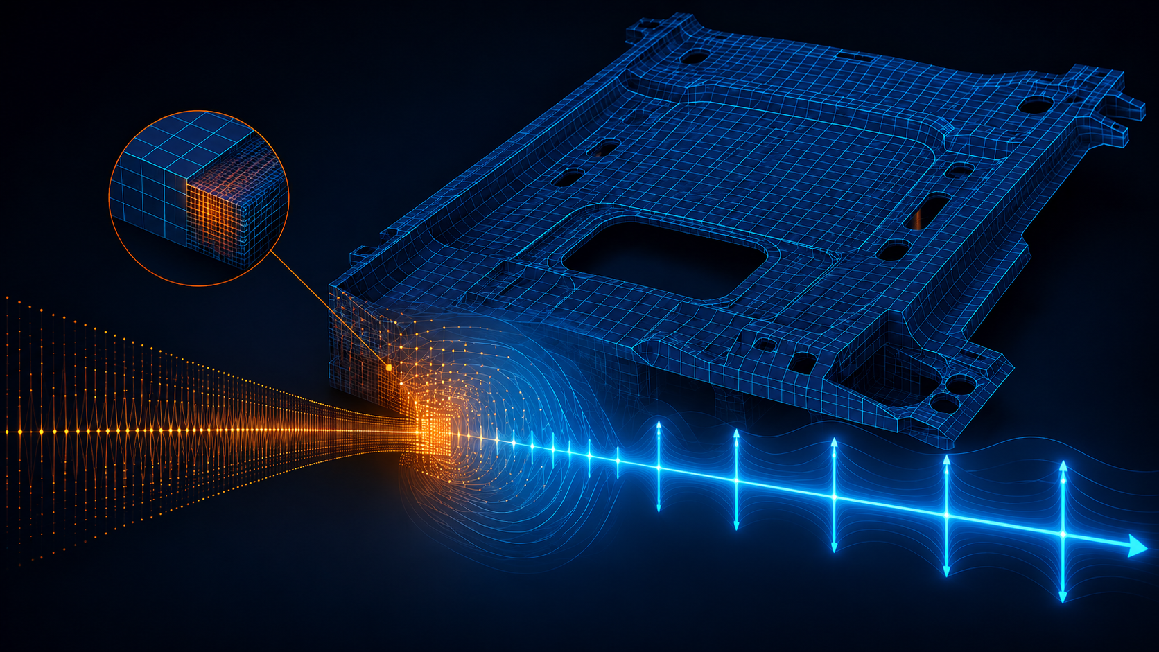
Discrete geometry
Finite elements and nodes form the basis of the geometry of the model structures. Each element in the model represents a separate part of the structure, which in turn consists of multiple elements connected to each other. Elements are connected to each other by common nodes. The coordinates of nodes and the way elements are connected (which shows which node belongs to which element) form the geometry of the model. All the elements and nodes in a model are created from the meshing of the members. Usually, meshing only approximates the actual shape of the structure. The element type, shape, position and number of elements used in mesh modules affects the results of analysis. The finer mesh (i.e., large number of elements) presents the more accurate result of job. When the mesh size becomes finer, the analysis results tend towards a single solution and the time required for the analysis also increases. The answer obtained from the numerical model is usually an approximate answer from solving the problems that have been simulated. The extent of the approximations depends on the geometry of model, behavior of materials, boundary conditions and loading, and these parameters determine the accuracy of the numerical answers compared to the experimental one. Of course, it should be noted that the user should always evaluate the sensitivity of his numerical model to the size of mesh seeds in order to choose the most optimal size for expanding his numerical models. The following video tutorial, produced by the Structural Numerical Research Center, teaches you this matter in the form of a simple example.
Characteristics of the elements cross section
Abaqus software includes a wide range of elements. Many elements have a geometry that is not completely determined by the coordinates of their nodes. For example, the layers of a composite shell or the dimensions of an I-shaped section are not defined from the elements' nodes. These additional geometrical data are defined as the properties of the cross-sectional area of the elements and are needed to build the complete geometrical model of the problem.
Material data
One of the important data that must be specified for an element is the characteristics of their materials. Because the preparation of detailed material data; especially in the case of models using materials with complex behavior; is a difficult matter, the verification of Abaqus results depends on the accuracy and availability of material data.
Loads and support conditions
Loads deform the structure and cause tensions in the structure. The most common types of loading are:
- Concentrated loads
- Compressive loads on surfaces
- Extensive tensile and contraction loads on surfaces
- Loads and linear moments on the edges of the shells
- Volumetric forces such as gravity
- Thermal loads
Boundary conditions are applied to create constraints on parts of the model so that the model remains fixed or moves by a predetermined amount.
In static analysis, sufficient boundary conditions must be provided to prevent the movement of the model as a rigid body. Otherwise, the motion of the unconstrained rigid body will cause the stiffness matrix to be invertible, and this will cause the analysis of the structure to be interrupted (aborted) before completion. The Abaqus/standard issues a warning message if model encounters a problem in the analysis during simulation. In these cases, it is necessary for users to evaluate warning messages. If during the static analysis, warning of irreversibility of the stiffness matrix is observed, it should be checked whether the structure or a part of it has experienced the movement of rigid body due to the lack of support constraints or not. The motion of a rigid body can be both translational and rotational. In the dynamic analysis of inertial forces, as long as all the individual members of the model have mass, it prevents sudden unlimited movement; Therefore, solution warnings in a dynamic analysis usually indicate the presence of other problems in the model, such as excessive plasticization.
Type of analysis
As mentioned earlier, Abaqus software can perform various types of simulations, and in this educational article, due to the nature of most engineering problems, only two types of static and dynamic analysis will be mentioned. We know that in a static analysis, the long-term response of the structure or member to applied loads is obtained and such analyzes are not dependent on time. On the other hand, at other times, the dynamic response of the structure, including the history of displacements and forces, is desired by user.
Choosing the type of analysis and mastering its concepts is very important. Because some elements are defined only for explicit analysis and others for implicit analysis in the software library. On the other hand, choosing a static or quasi-static solution method can have a significant impact on the problem-solving time.
Soon, in another educational article, we will explain the standard and explicit solution method in detail. In this article, we reviewed the basic concepts, requirements and processes of Abaqus software, and if you are a beginner in this software, you need to consult with an expert. For more than 13 years, Structural Numerical Research Center has been active in the field of numerical simulation of mechanical, structural and geotechnical engineering problems. Some of our educational models can be obtained in the link and numerical modeling techniques are provided in step-by-step form. Keep in mind that to increase your modeling knowledge in Abaqus software, the best reference is the software help, along with the tutorials on our website.